Señor Drinknstein Comes to LIFE
Señor Drinknstein started with an idea to use peristaltic pumps to serve various beverages, and has become so much more. For DEF CON 30 we worked to create a system of hardware and firmware that would give the end user a memorable experience while serving them a unique drink in a unique way at a unique event around unique people.
Because this is a finished project and I am ~lazy~ efficient, I’m going to type everything up here in most likely one go. GLHF, watch me for the changes and try to keep up.
So it all started in the Winter of 2021 when one of my friends said “Hey, I’ve got this idea for a robot that serves drinks, it uses peristaltic pumps to move things around in a sanitary fashion”. Full stop. Verbatim, I’m sure that’s how it went. Anyways, next thing we know we’re testing flow rates with pumps and trying to figure out how we’re going to bring this thing to life. For those of you who don’t know what a peristaltic pump is, it’s the same kind of pump used in medical facilities to move bodily fluids around.
 Figure 1. Model of how a peristaltic pump works
Peristaltic Pump (from Internet Glossary of Pumps)
As you can see above, we can use a silicone tube (our chosen food-grade material) to transport liquids from one location to another without ever touching the liquid. You can see how this would be helpful when moving around sticky things like juices and mixers, and even gasp alcoholic liquids! From this proof of concept, we had an idea of where to start.
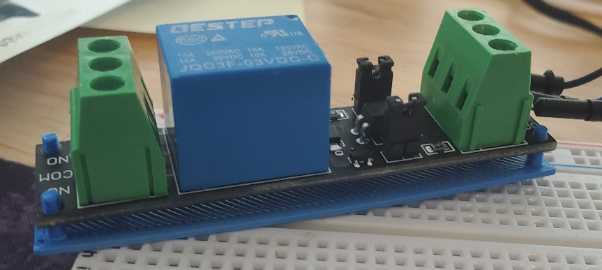 Figure 2. A picture of the relay we were testing on top of a custom 3d printed mount I designed for it in OpenSCADasdf
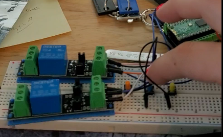 Figure 3. Testing a couple of relays
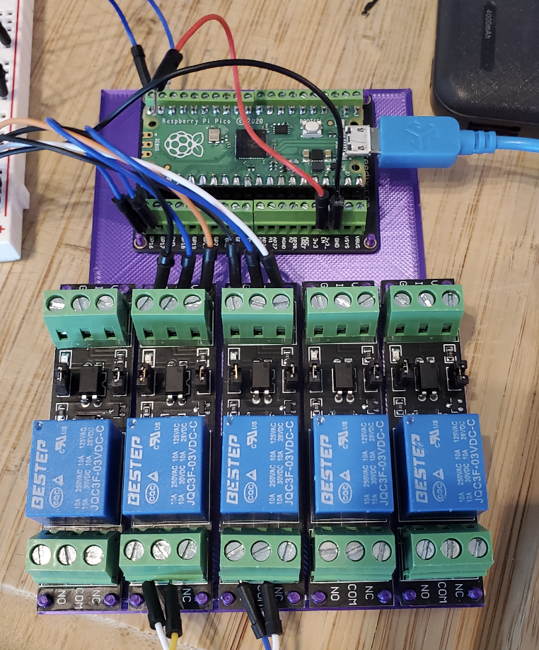 Figure 4. Testing a full mounting bracket for a Pi Pico with 5x of our relays
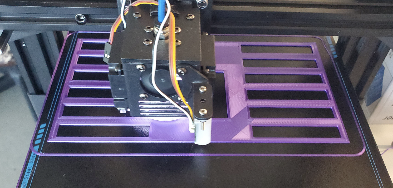 Figure 5. Printing a board to support up to 12 relay-controlled devices
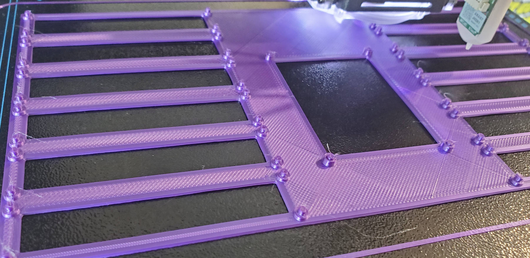 Figure 6. Attempt at printing ‘circuit board’ with melt-in-place pegs for all the components
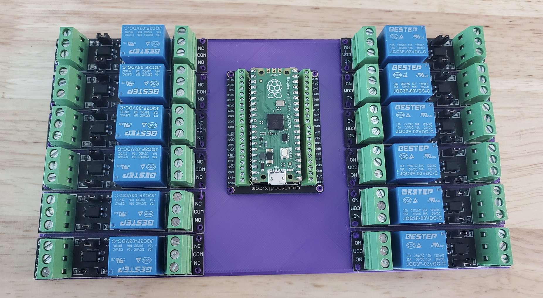 Figure 7. First prototype of Pi Pico mounted together with 12 relays using melt-in-place pegs
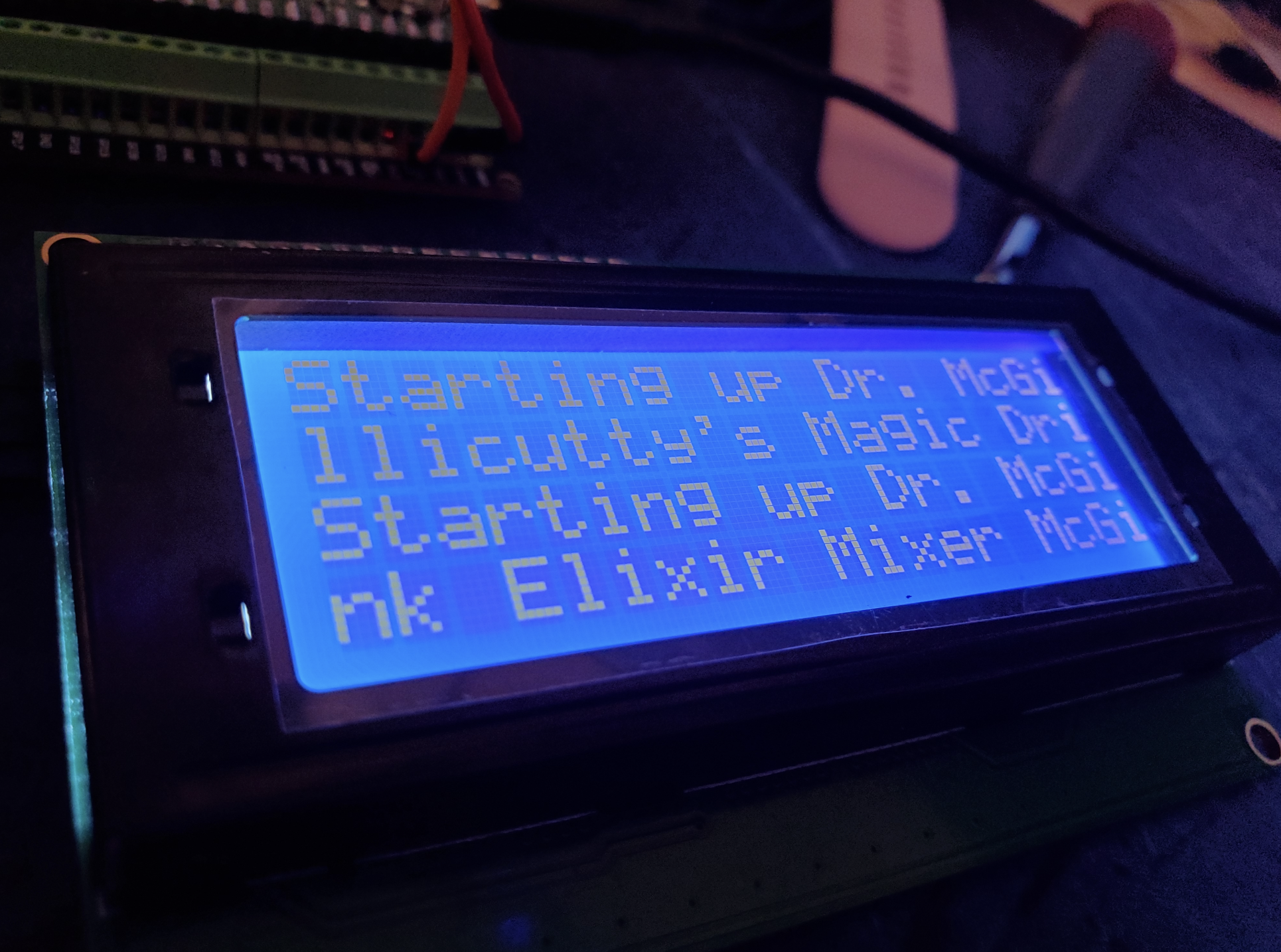 Figure 8. First go at loading code on to the chosen screen for the robot
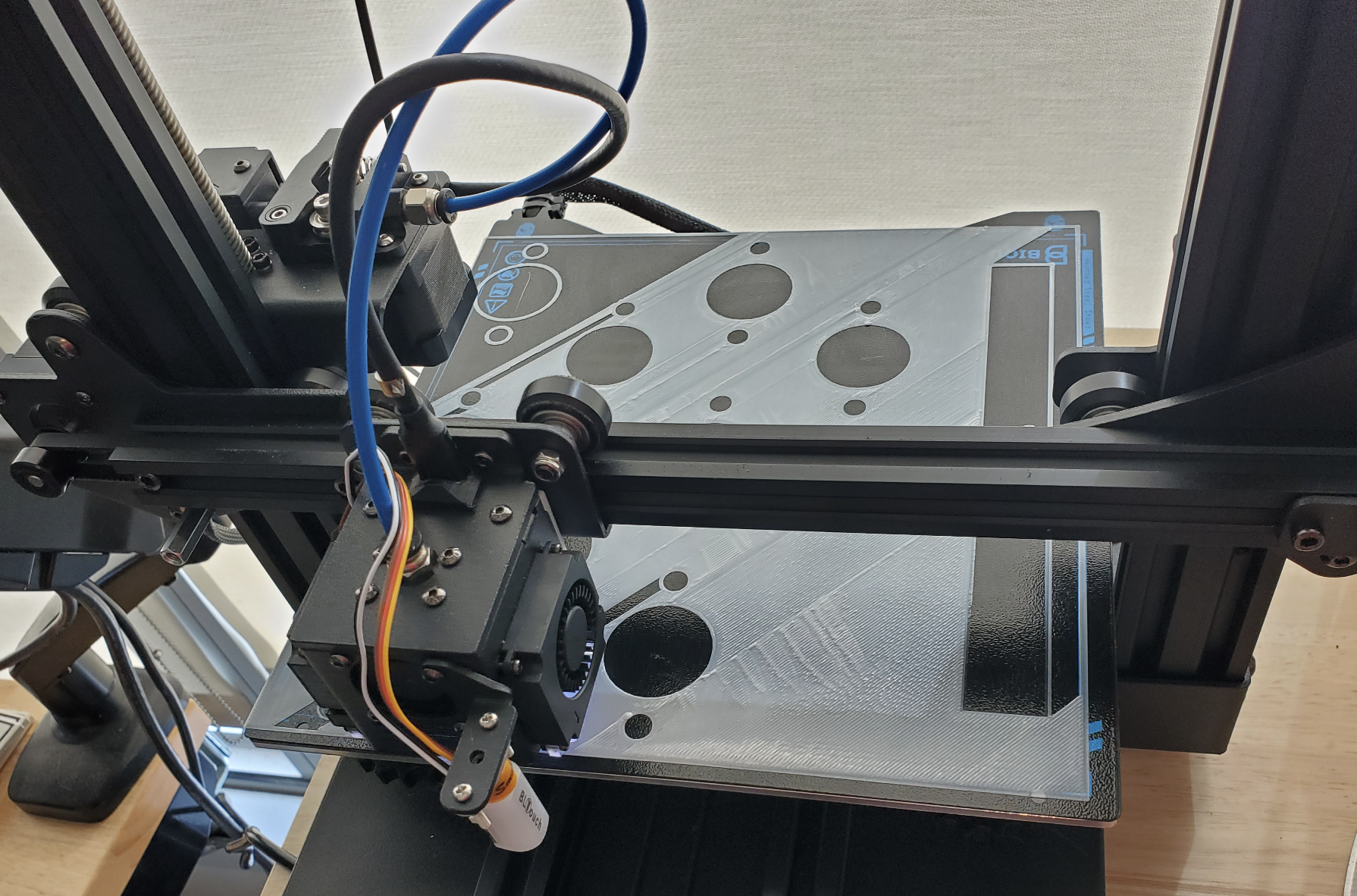 Figure 9. First prototype housing for mounting 9 peristaltic pumps to one common chassis
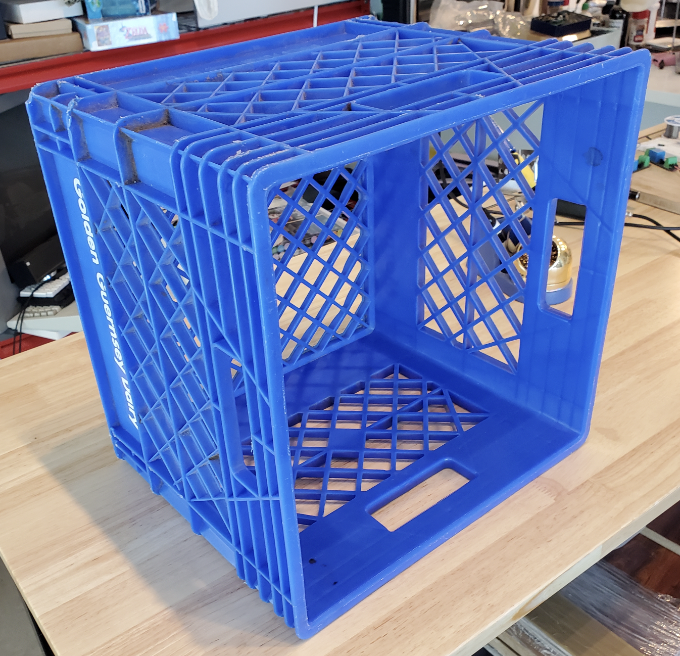 Figure 10. Proposed housing for all of the robot’s guts
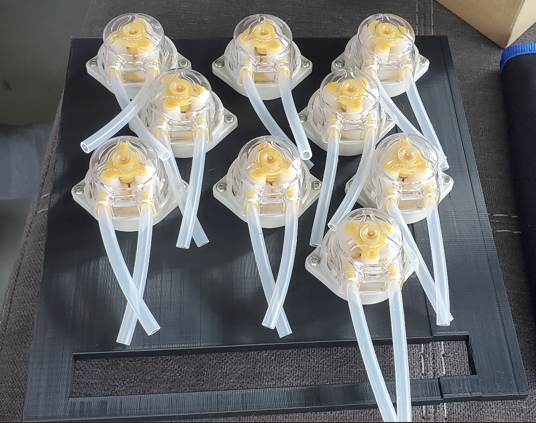 Figure 11. Final print for one of the bot’s peristaltic pumps. Yes it shifted mid print near the end, but I wasn’t going to throw it away.
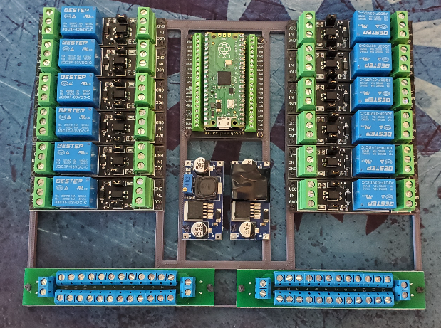 Figure 12. Semi-final print of “circuit board” using melt-in-place pegs to seal parts down. This would come to be an issue as we needed to remove the parts at some point and you cannot do that without being desctuctive with this methodology.
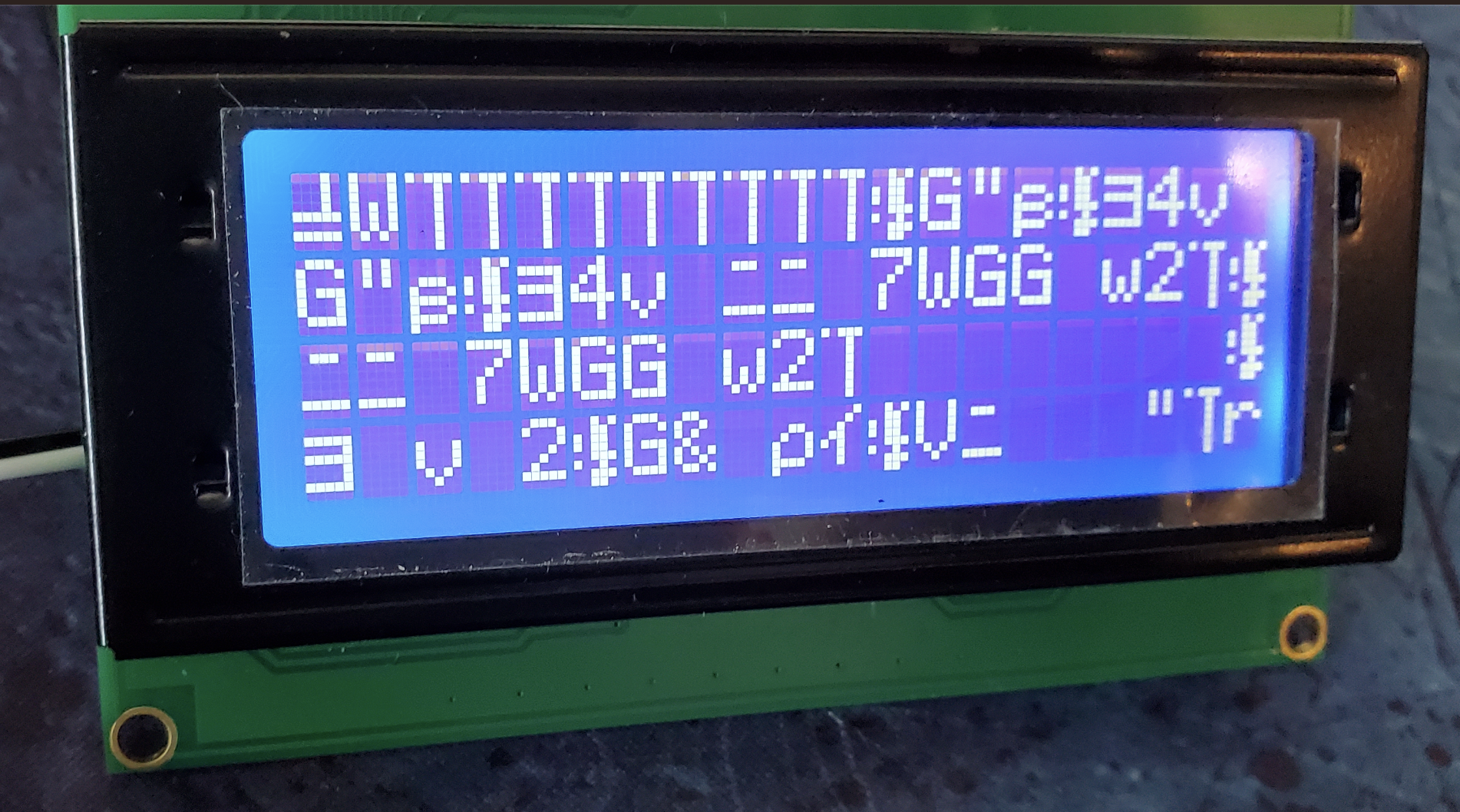 Figure 13. Errors on these LCDs are a lot of fun, here’s one we got when we were adding animations to things!
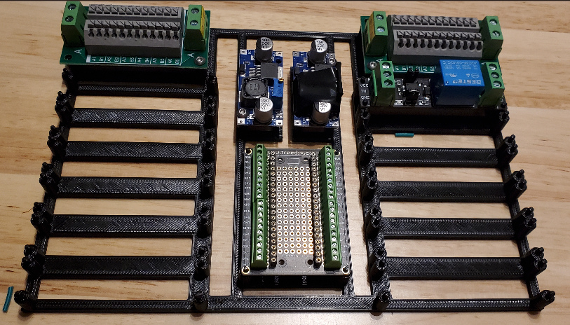 Figure 14. Screws hadn’t come in yet so we used the pegs for now while finishing up the final designs
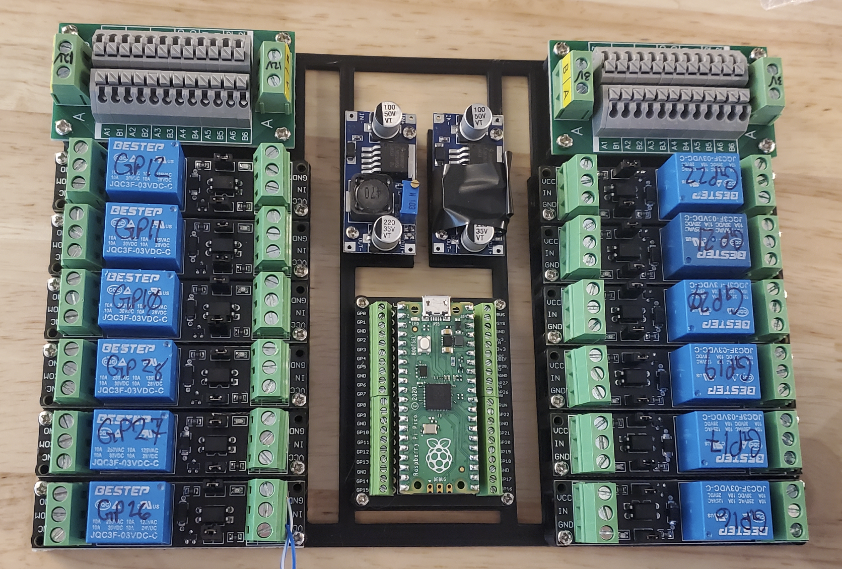 Figure 15. First completed board before wiring everything up to the appropriate GPIO pins
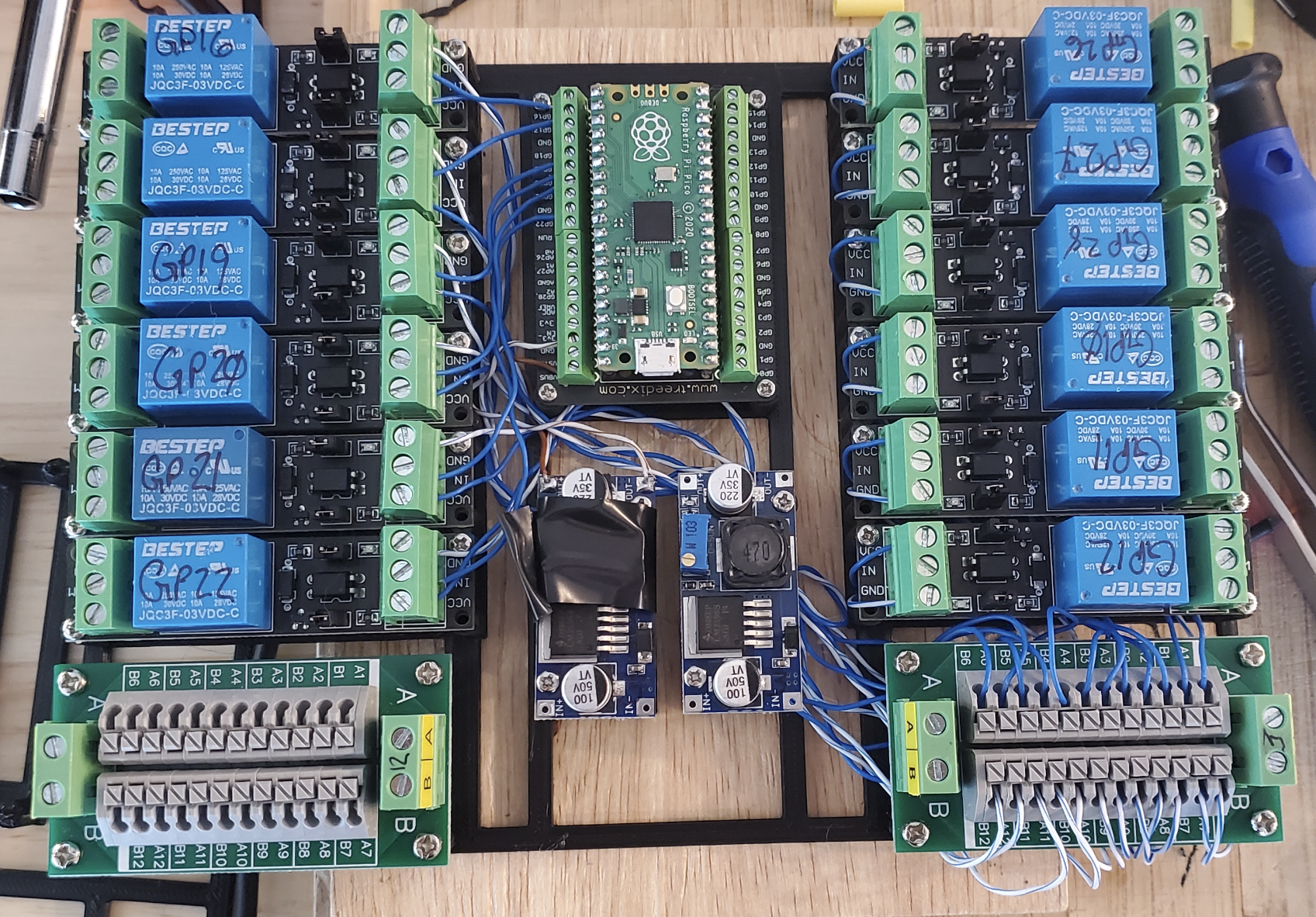 Figure 16. Wiring up the ratsnest of cabling! This is where our 3.3v relay cables start to show issues with randomly triggering the GPIO on their modules due to a grounding issue between the pins and the pi’s ground. Not sure exactly what the issue was but will dive more in to that later. Fully wired up the 3.3V and 5V adjustible-voltage-limiters along with a 3.3v rail for powering all the relays. The 5v voltage-limiter is there to power the pi through VSYS
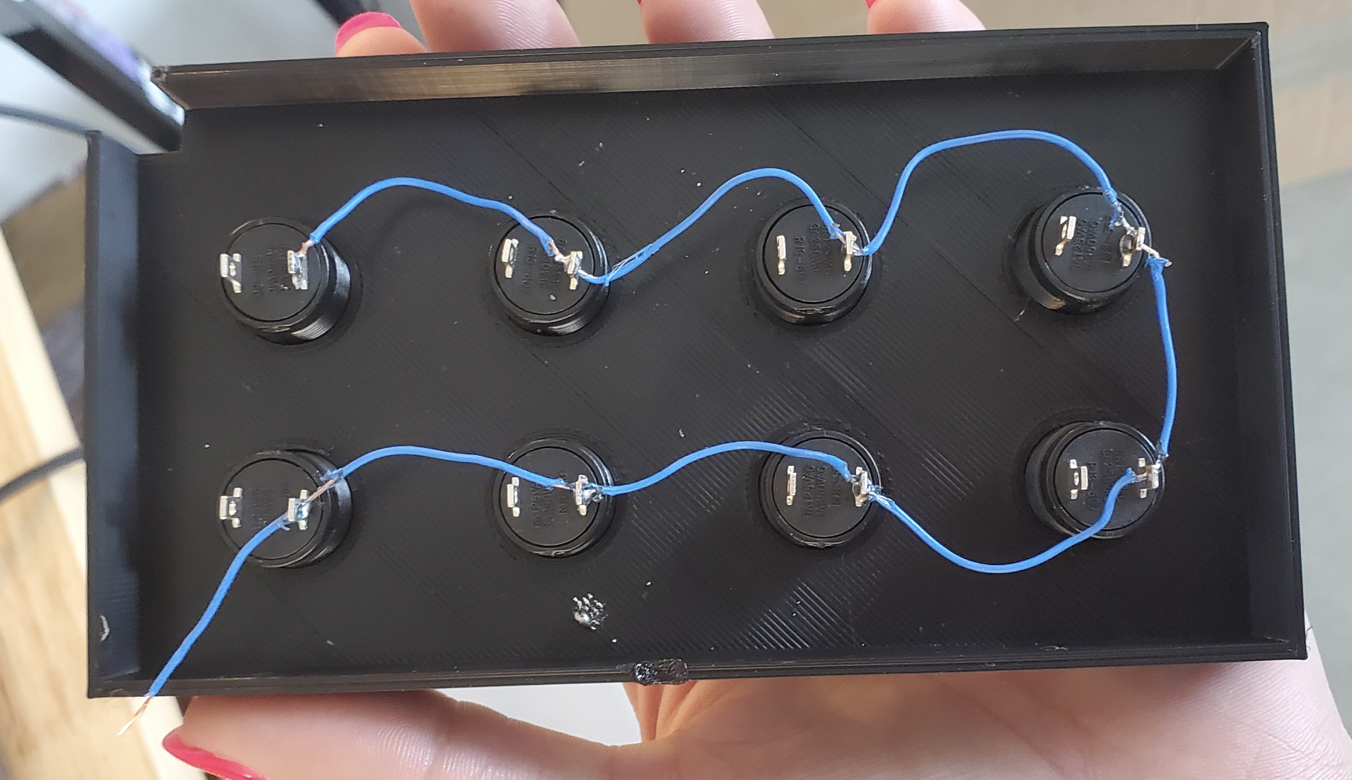 Figure 17. Wiring the common ground for the push-buttons
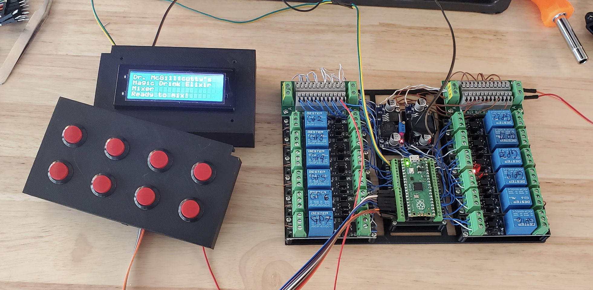 Figure 18. Pushbuttons all wired up!
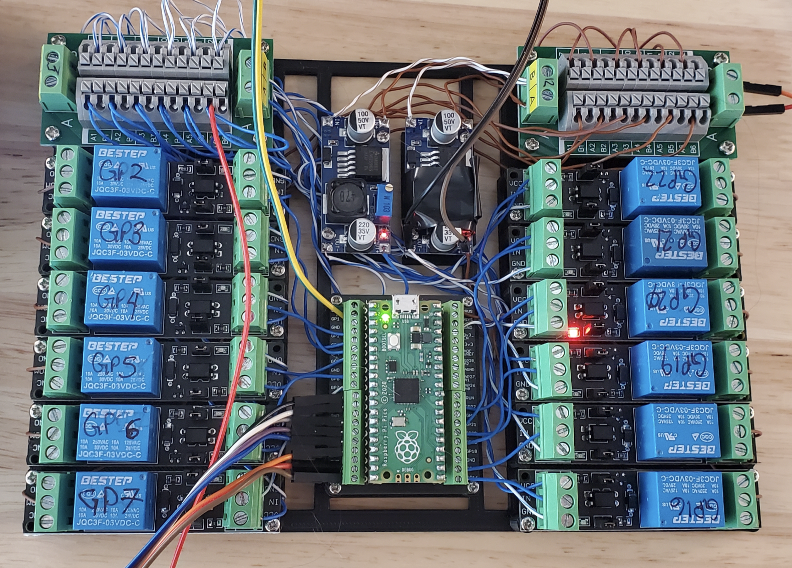 Figure 19. Things are starting to get messy with adding the buttons and screen to their proper pinouts
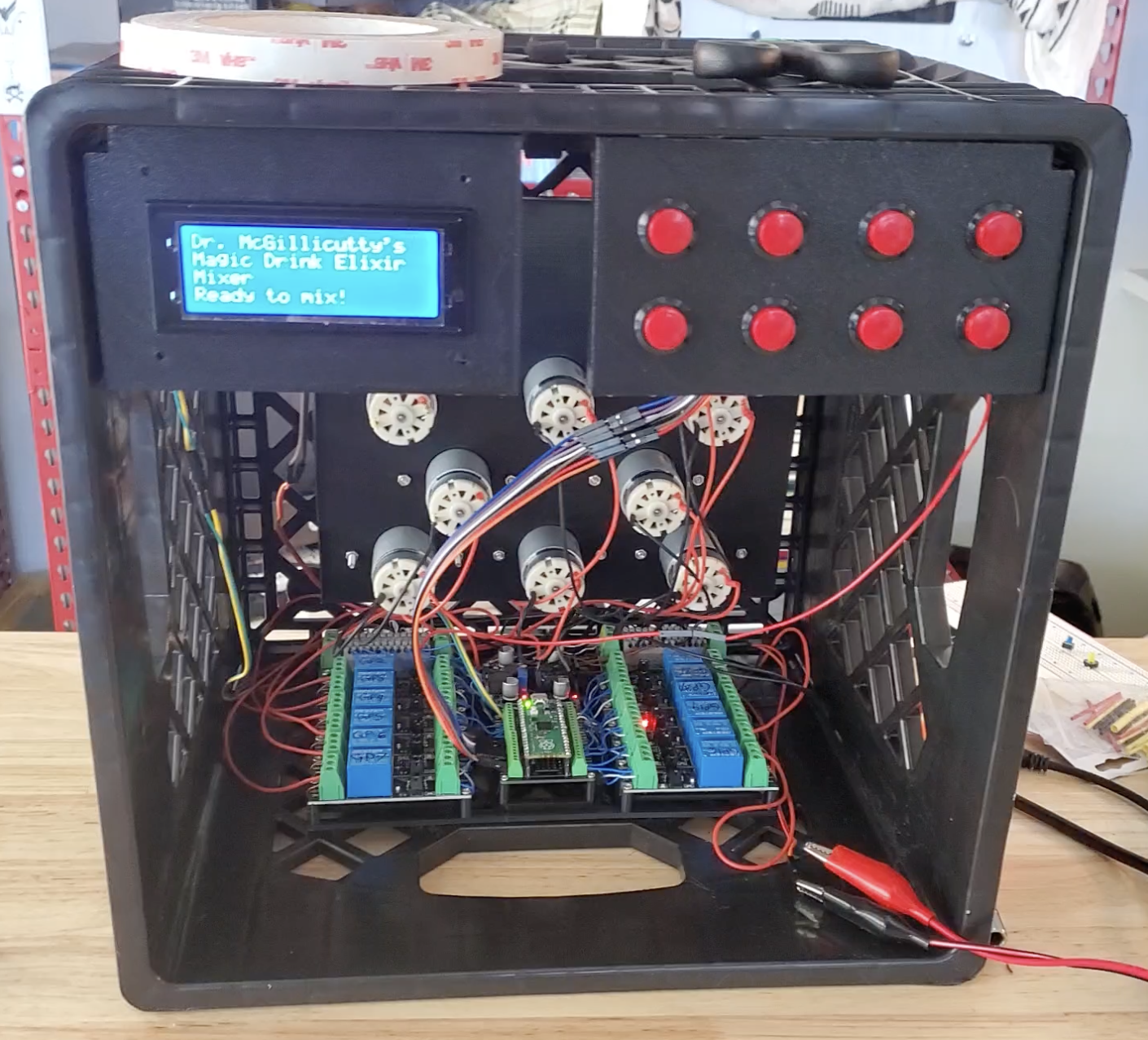 Figure 20. The first test fit of the buttons, screen, pumps, and circuit-board inside of the LEGALLY ACQUIRED milk crate